


THIS APPLICATION NOTE
- Is intended to help designers verify the shape of current pulses from ESD simulators prior to compliance or precompliance testing
- Covers some basic theory on ESD
- Describes a basic testing system for ESD simulators with an oscilloscope
- Explains how to verify pulses for contact discharge testing and air discharge testing
This application note uses a 6 Series MSO oscilloscope to illustrate techniques for ESD troubleshooting. Setups and measurements will be practically identical for comparably equipped 4 and 5 Series MSOs, since they share the same controls as the 6 Series MSO. Many of techniques described herein may be used with any professional-grade oscilloscope with appropriate performance, especially rise-time.
Introduction
Testing for electrostatic discharge (ESD) immunity is critical when designing products for compliance with worldwide electromagnetic compatibility (EMC) standards. The primary international standards referenced for most products include IEC 61000-4-2 and the U.S. ANSI C63.16, which specifies how to set up and perform these ESD tests [References 1 and 2]. An ESD simulator is required to produce accurate and repeatable test pulses.
The standards also specify the shape and timing of the current pulse you must inject into your equipment under test (EUT). Before running an immunity test, you must verify that your ESD simulator produces a current pulse with the proper shape and rise time. You can verify a simulator's performance by using a calibrated ESD target and a high-bandwidth oscilloscope. The Tektronix 4/5/6 Series MSOs are ideal for this verification measurement.
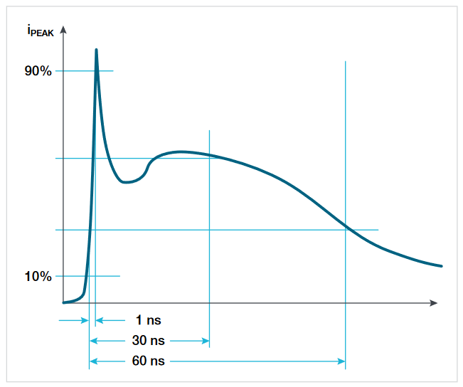
ESD generated from a person touching an enclosure or a cable can disrupt the circuits in electronic systems. As a person's finger approaches a metallic object, a typical human-body ESD event creates a high-current discharge into the object. The resulting current pulse may amount to several amperes at a very high leading edge with a rise time of less than 1 ns (Figure 1).
The idealized ESD waveform is shown in Figure 1.
The human body can be modeled as a simple series RC network (Figure 2). As the electric charge builds, the capacitor charges to the selected number of kV. When the switch (simulator trigger) is flipped, this charge discharges rapidly into the EUT. Several manufacturers offer simulators that reproduce current waveforms very close to this humanbody model. The wave shape these simulators must generate is specified in the IEC 61000-4-2 international standard.
IEC 61000-4-2 requires that you verify the ESD simulator's tip voltage before testing your EUT. It also requires that you verify several characteristics of the resulting current waveform, such as current peak, current reading at 30 ns, and current reading at 60 ns.
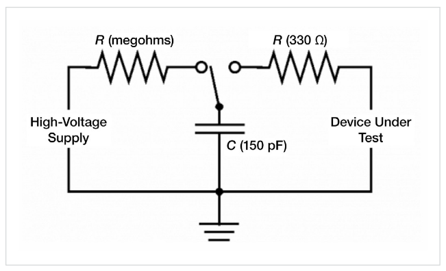
The simulator's tip voltage may be measured with an electrometer or gigohm meter [Reference 3]. However, most have found that for simple pre-compliance verification tests, a high-impedance, high-voltage resistive voltage divider (of 100 MΩ in series with 1 MΩ) and a digital voltmeter may be used. Make sure the resistors can withstand up to 25 kV.
The IEC and ANSI standards place more stringent requirements on measurement repeatability than they do on the rise time. To capture ESD, you must set your oscilloscope to “single-shot” mode. If the oscilloscope returns a range of different answers for repeated rise-time measurements, then you can't depend on it to accurately measure the rise time on any one occasion—even if the average of many measurements is highly accurate. A major factor in single-shot repeatability is low internal noise, so compare noise specifications when you evaluate oscilloscopes for ESD testing. The 6 Series MSO used in these examples has particularly low noise contribution and is well-suited for these tests.
Use a shunt - To check an ESD simulator's output, you must measure the waveform of the resulting current across a low-impedance, high-frequency resistive shunt connected to ground. This shunt, or ESD target, emulates a discharge into a large metallic object such as an equipment enclosure (Figure 3).
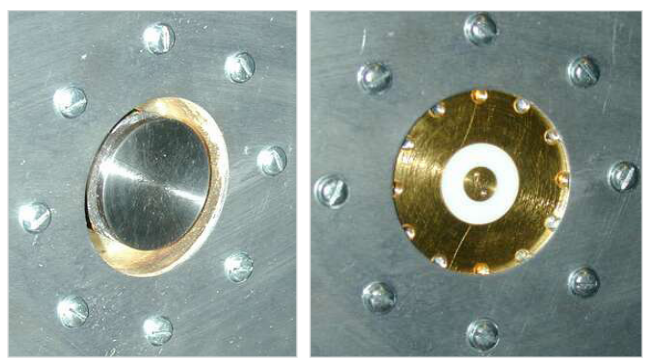
The IEC and ANSI standards currently specify a shunt impedance of less than 2.1 Ω, but that will change in future revisions. To help engineers more accurately verify ESD simulator performance, draft standards now specify a higherbandwidth, lower-impedance calibrated (newer) ESD target. The new target has an impedance of about 1 Ω. Today, the IEC and ANSI standards specify a 1 GHz bandwidth target. The draft standards specify a 4 GHz bandwidth target.
When setting up your test, you must mount the target in the center of a 1.2 m2 ground plane. ANSI C63.16 target specifications include a reflection coefficient of less than 0.1 (equivalent VSWR of less than 1.22) and an insertion loss of less than 0.3 dB up to 4 GHz. These targets may be purchased commercially.
To complete the test setup, you'll need cables, attenuators, and an oscilloscope. Use good-quality low-loss cables between the target, the attenuators, and oscilloscope. Keep the total cable length less than 1 m so you comply with the IEC and ANSI standards. ANSI C63.16 requires a doubleshielded cable that prevents signal leakage from affecting your measurement. It also recommends RG-400/U cable, but RG-214/U—although twice the diameter—has half the loss and seems to work well. You can also use any gigahertzbandwidth coax cable.
IEC 61000-4-2 also specifies that you place the oscilloscope inside a Faraday cage to shield it from ESD-induced radiated emissions. During the time the standard was developed (early 1990s), many engineers made these measurements with analog phosphor storage oscilloscopes. The standard specified a shield to prevent distortion in the displayed waveform on an analog oscilloscope. The shield also minimized false triggering caused by fields emitted from the discharge.
Today, most high-speed digital oscilloscopes, including the Tektronix 4/5/6 Series MSOs, have well-shielded input circuits, so the Faraday cage is usually not required in practice. Simply mounting the ESD target in the center of a 1.2 m2 sheet of aluminum usually prevents unwanted triggers in digital oscilloscopes.
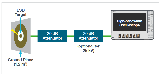
The block diagram of the test setup is shown in Figure 4. You'll need attenuators to protect your oscilloscope's input preamplifiers, because the ESD target can produce voltages greater than 50 V. A 20 dB attenuator is convenient because it represents a 10× attenuation and you can simply multiply the measured voltages by 10 to find the actual voltage across the shunt, then calculate the resulting current. Your attenuator must be capable of handling up to 50 V spikes, and its bandwidth must accurately pass frequencies up to 4 GHz.
Choosing an oscilloscope - When choosing an oscilloscope, look carefully at an instrument's bandwidth, rise time, and noise. To accurately measure the signal without sampling errors, an oscilloscope must have sufficient bandwidth. For a Gaussian-response oscilloscope, you may need a sample rate up to six times the oscilloscope's bandwidth, although four times the bandwidth is more typical.
With a digital oscilloscope, you must also pay attention to sample rate. A digital oscilloscope has a flatter response over its usable bandwidth, and it has a sharp roll-off above its 3 dB frequency. Thus, you need a sample rate of 2.5X the oscilloscope's bandwidth to avoid alias errors.
In order for an oscilloscope to accurately display an ESD pulse's rise time, it must have sufficient bandwidth and rise time. The rules for determining whether a scope's specifications are adequate differ for analog and digital models [Reference 4].
For analog oscilloscopes, the generally accepted rise time and bandwidth rules were:
- Bandwidth = 0.35/(rise time), or rise time = 0.35/bandwidth.
- The oscilloscope must have less than one third the rise time of the incoming signal in order to measure the rise time with an error of 5% or less.
For digital oscilloscopes, use the following calculations:
- Bandwidth ≈0.43/(rise time)
- The oscilloscope's rise time only needs to be ~0.7 times the rise time of the signal in order to measure rise time with an accuracy of a few percent.
The flatter frequency response of most digital oscilloscopes enables them to produce less attenuation at frequencies below the –3 dB point than analog oscilloscopes do. Thus, digital oscilloscopes produce more accurate measurements. Secondly, the steeper roll-off of digital oscilloscopes helps reduce aliasing errors.
Typically, a human-body ESD pulse can have a rise time of less than 200 ps. The bandwidth required to accurately display this would be approximately 0.43/(200 ps), or 2.15 GHz. Some ESD simulators can produce rise times of 50 ps and thus require an oscilloscope bandwidth of 8.6 GHz.
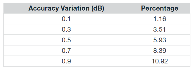
The target-attenuator-cable chain will produce some loss of signal amplitude. Variations in loss from one test setup to another must be ±0.3 dB from DC to 1 GHz and ±0.8 dB from 1 GHz to 4 GHz. Table 1 shows that systemaccuracy variations of less than 1 dB can greatly affect measurement accuracy.
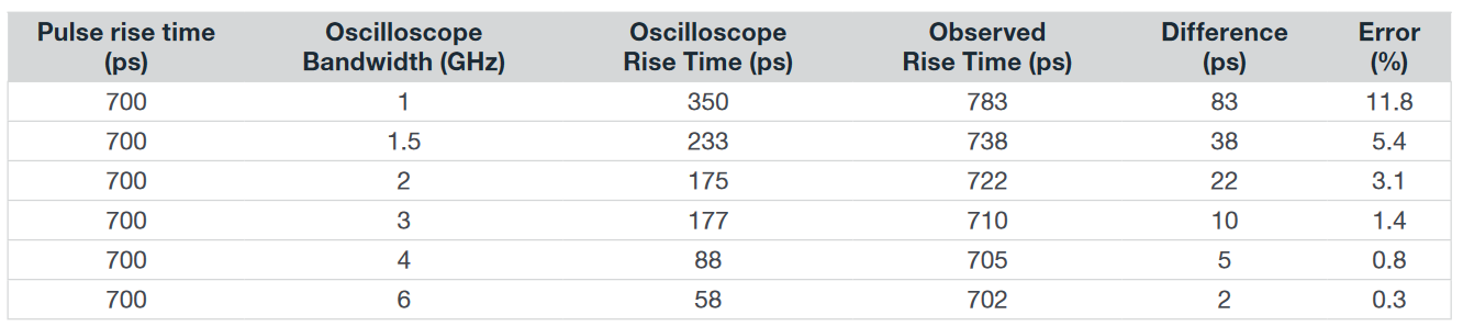
The higher an oscilloscope's bandwidth, the more accurately it will capture the ESD pulse's rising edge. Table 2 shows that an oscilloscope's rise time directly affects the measured rise time of an ESD pulse. For a pulse with a rise time of 700 ps, you need an oscilloscope with at least 4 GHz bandwidth to get less than 1% error. You must add this error to any system errors when you measure rise time.
To measure an ESD pulse, set the oscilloscope to single-shot mode and use a positive-edge trigger. Set the trigger level just above zero. You may need a minor trigger-level adjustment to capture the entire waveform. Set the vertical sensitivity to either 200 mV/div or 400 mV/div (depending on the simulator voltage selected) and set the time base to 20 ns/div. Assuming the measured signal is a triangle (for simplicity in calculations), a measured rise time of 800 ps will require a 10 Gsamples/s sample rate, which equates to 100 ps/sample, or eight samples on a rising edge, enough to accurately represent it.
Verifying Contact Discharge
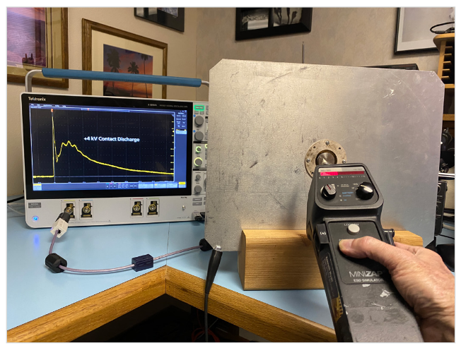
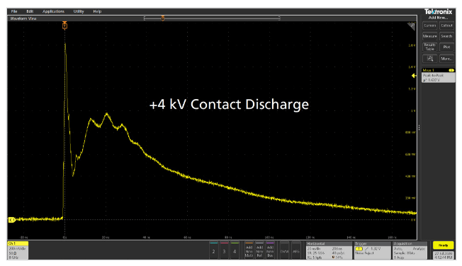
Most ESD standards will specify a contact discharge test level of ±4 kV for most products, but this can vary due to application or usage environment. In Figure 5, we're demonstrating the capture of a +4 kV contact discharge pulse. The simulator ground wire should connect to the ground plane. For contact-discharge tests, place the tip directly on the target prior to triggering the simulator.
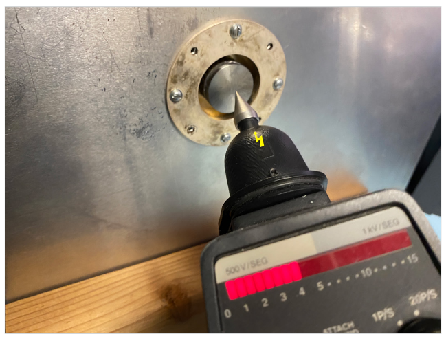
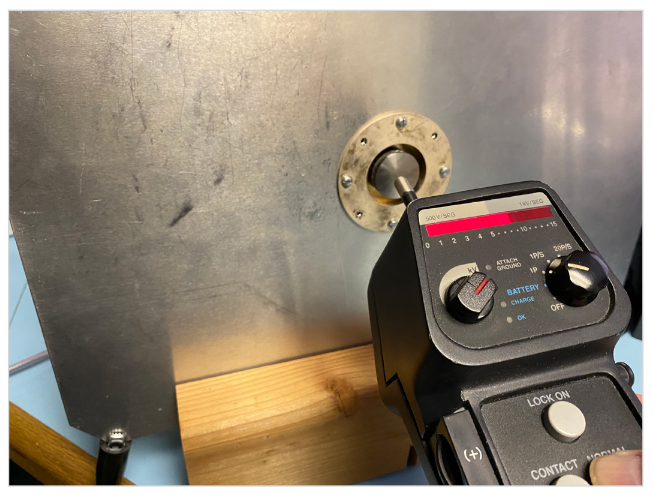
During actual verification testing try to keep the simulator ground wire far away from the oscilloscope coax to prevent cable-to-cable coupling. The standard recommends grabbing the ground wire in the middle and pulling it away from the ground plane. Keep the contact discharge tip centered in the target (Figure 6)
To capture ESD pulses on the 4, 5 or 6 Series MSO, adjust the vertical scale to 200 or 400 mV/division (depending on the voltage setting of the simulator) and the horizontal time base to 20 ns/division to capture most of the wave on the screen. Set the trigger mode to “Manual” and set the trigger level above or below the zero-volt baseline, depending on whether you're verifying a positive-going or negative-going pulse (Figure 7).
Verifying Air Discharge
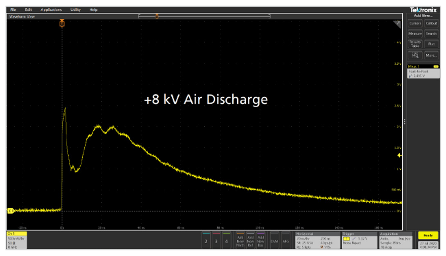
Most ESD standards will specify an air discharge test level of ±8 kV for most products, but this can vary due to application or usage environment. In Figure 8, we're demonstrating the capture of a +8 kV contact discharge pulse

Approach with care - Air discharge verification can vary considerably and is dependent on approach speed, approach angle and humidity. When executing your tests using air discharge, try to approach the target with the ESD simulator from a 90° angle and at a constant speed (Figure 9). Allow the tip to arc to the target without actually touching the target. You'll maximize repeatability, but can expect to see a lot of variation in wave shape and peak voltage. The humidity during the demonstration examples was 45%, which can tend to lower the peak voltage measurement from normal. During your air discharge testing you may want to document the humidity as it can have a significant effect on the results of your ESD testing. This variation is one reason contact discharge testing is required, because it is inherently more consistent in rise time and pulse shape. Figure 10 shows the 8 kV air discharge capture.
Summary
Be sure to perform and document your verification test prior to any pre-compliance or compliance test to prove proper simulator operation. Once the verification tests are complete, the investigative or qualification testing may be performed, knowing that your ESD simulator is working properly.
The Tektronix 4, 5 and 6 Series MSOs are ideal for this verification measurement due to their exceptional bandwidth and low internal noise.