

By Matt Benes, Technical Marketing Manager, Tektronix
Modern development boards are amazing tools that have put the power of the microprocessor into the hands of hobbyists and entrepreneurs everywhere. These development boards are capable of handling multiple inputs including analog and digital, storing data, and running powerful programs. But what do you do when one board is not enough? What if you want to connect multiple devices and sensors to a single board and turn that already versatile board into an even more powerful system? Luckily there are many different methods to connect these devices. In this post we will discuss some common ways to do this using a wired connection. We will cover wireless communication in a future post.
The two primary methods for data transfer are serial and parallel communications buses. Serial uses a single channel to send data bits one after another while parallel uses multiple channels and sends multiple bits concurrently. For the purposes of this article we will focus on serial communication because it is more commonly used for development boards. One of the reasons for this is that serial communication takes up less space which is often limited on development boards. Three common methods of serial communication we’ll discuss here are SPI, universal asynchronous receiver/transmitter (UART), and I2C. Each interface has advantages and disadvantages depending on the application.
SPI
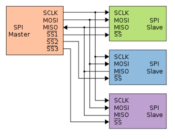
Serial Peripheral Interface (SPI) is a serial interface that can be used by microcontrollers and other peripherals such as sensors to send data to one another. SPI utilizes a clock line, data line, and a select line that is used to select the appropriate device you wish to communicate to in the case of multiple connected devices. SPI is capable of the fastest speeds out of the three interfaces we cover here and is capable of handling multiple slaves from a single master device. One drawback of SPI is that compared to other methods it requires more wires and as you add additional devices the number of wires can quickly become burdensome.

UART/Serial Ports
Serial ports use an asynchronous method to communicate between two devices and is commonly seen on many development boards. Most development boards will come with a standard asynchronous serial port that can be used for a simple connection between two devices. Some will prefer this method because of its simplicity, but there are downsides to using the serial port. Since it is asynchronous (no clock is being transmitted), both devices using the serial port must be programmed ahead of time to use the same data rate or the data will be corrupted. Another downside is it can only be used for communication between two devices and two only.

I2C
Inter-Integrated Circuit (I2C) is a two-wire design that has found its way into a wide variety of chips and can be found in many designs today. I2C uses a bi-directional serial clock and data lines and supports three bit rates: 100 kbps standard mode, 400 kbps fast mode and 3.4 Mbps high speed mode.
Data and clock are sent from the master and the data is clocked on the rising edge of SCLK. I2C supports multiple masters and slaves on the bus, but only one master may be active at any one time while slaves can transmit or receive data to the master.
Each device is recognized by a unique address and can operate as either a transmitter or receiver, depending on the function of the device. I2C sits in the middle of the previous two methods. Because of this versatility it is helpful to use an oscilloscope, as we discuss next, to monitor an I2C signal and decode the data on the scope to verify the connection.

Example – Here’s how to validate I2C
When designing a system that utilizes an I2C bus you will often come across the need to verify that data being transmitted across the bus is the correct data. Using an MSO/DPO2000B oscilloscope you can not only view the signal but can also trigger on events of interest. With the DPO2EMBD application module you can decode the data using software, saving you the time that it would take to decode the data bit by bit manually. These capabilities can save you hours of work by enabling you to easily find, capture, and analyze events of interest on your serial data.
For more insights, but sure to check out the Serial and Parallel Bus Decode Video.

Since publishing the above blog, Tektronix is currently offering discounts up to 89% on software application modules for qualifying oscilloscopes. Check out the details here and save away!