

By Xiao Li
Sophisticated RF electronic components in automobiles have resulted in much safer, efficient, and connected vehicles. They have also created new challenges for RF testing and verification. In this two-part series, we will discuss the ins and outs of testing common RF automotive applications: Tire Pressure Monitoring System (TPMS), Remote Keyless Entry (RKE), Passive Keyless Entry (PKE), and Remote Start (RS). In this post we review the block diagrams and take a look at the RF physical layers of these systems. In part 2 we’ll examine test procedures for transmitters, receivers and EMI pre-compliance.
Automotive RF systems all use similar architectures and components with some variations to fit the application at hand. Here is a rundown.
We’re all familiar with Remote Keyless Entry (RKE) where an RF transmitter on the key fob is used to replace the traditional mechanical car key. Gaining in popularity is Remote Start (RS) functionality that allows drivers to start and stop the engine remotely. As you might expect, the block diagrams of RKE and RS systems are similar. A simplified version is shown below. Pressing a button on the key fob wakes up the controller or CPU inside the key fob, which sends a signal to the RF transmitter. The receiver in the car captures and demodulates the signal and send the appropriate command to the controller to either open the doors or start the car. The block diagram can be also applied to other similar applications, like Garage-door Opener (GDO).

Now let’s take a look at Passive Keyless Entry (PKE) and Passive Start (PS) systems that lock and unlock doors and start and stop the engine without direct key fob input. Such systems are similar to Tire Pressure Monitoring System (TPMS) systems that warn drivers when tires are significantly under inflated. The block diagram for PKE, PS, and TPMS is shown below. Compared RKE/RS, these systems add a trigger, IF initiator and IF receiver to the system.

For PKE and PS, the trigger system activates when user approach the car or touches a button on the door handle. Then the car transmits a Low Frequency (LF) signal with encrypted message to the LF receiver in the key fob, and the key fob sends an RF signal to the car to request the doors to be opened or closed and engine to be turned on or off.
For TPMS, the controller in the car wakes up the sensor modules in each tire through the LF Initiator to poll the pressure, temperature data and checks the battery level in a sequential manner. If tire pressure is lower than it should be, the system illuminates an indicator light on the vehicle dashboard.
RF PHY layer
These communication systems span two frequency domains: LF and RF. Typically, the LF part uses a 125 kHz ASK modulated signal. The LF link communicates over a short distance (1 meter or less).
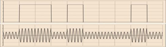
For the RF part, Amplitude Shift Keying (ASK) is a popular modulation scheme used in low-frequency automotive connectivity RF applications. The source transmits a large amplitude carrier when it wants to send a 1 and it sends a small amplitude carrier when it wants to send a ' in its simplest form. On-off Keying (OOK) modulation is a special and simplified version of ASK, where the source sends NO carrier when it wants to send a 0. OOK is very popular in battery operated devices because it saves on transmit power when sending 0s.


Another popular modulation in short range automotive RF applications is Frequency Shift Keying (FSK), which transmits 1s and 0s through the use of different carrier frequencies. A significant advantage of all FSK systems is that the transmitted signal has constant envelope, so more power-efficient class-C non-linear power amplifiers can be used in the transmitter. Also, this approach is more bandwidth efficient than ASK and OOK. However, the cost of FSK modulation is usually higher than ASK and OOK.

Most TPMS, RKE, PKE, and RS systems use one of the 'unlicensed' ISM bands (industrial, scientific and medical) as the carrier frequency, often around 434 MHz in Europe and 315 MHz in much of the rest of the world. The baud rate is flexible. It is usually between 2 kHz and 20 kHz. Normally, no pulse shaping filters are used. These systems are not based on specific wireless communication standards.
Now that you have a basic understanding of the terminology and architectures used in these systems, stay tuned for our next post where take a look at test procedures and equipment.
To learn more about how computing power is replacing horsepower in modern networked cars and the full range of Tektronix solutions for the automobile industry, go to: https://www.tek.com/automotive/trends