

Understanding Power and Signal Integrity
Testing power and signal integrity using an oscilloscope-based solution has some inherent challenges that need to be considered and resolved for optimum performance. We’ll address five of those here, but first let’s take step back and define what we mean by power and signal integrity.
Signal Integrity (SI) and Power Integrity (PI)
Signal integrity (SI) analysis concentrates on the performance of the transmitter, reference clock, channel, and receiver in terms of the bit error rate (BER). Power integrity (PI) focuses on the power distribution network’s (PDN’s) ability to provide constant, clean power rails and low impedance return paths. SI and PI have broad interdependencies. The PDN can cause noise and jitter. The circuit design and components—chip package, pins, traces, vias, connectors—affect the impedance of the PDN and hence the quality of the power supplied.
The Importance of Power Integrity
We know that introducing noise and jitter from power rails can cause bit error rates in high-speed serial networks, which at the very least can reduce the efficiency of those embedded systems. But at the worst, can lead to corrupted bits or corrupted data lines that fail in mission critical environments.
Power integrity is NOT just about keeping voltages within the appropriate limits. PI is the assurance that power applied to a circuit or a device is appropriate for the desired performance of the circuit or the device. Its purpose is to maintain the quality of power from generation to consumption. Achieving an acceptable power integrity implies the noise levels are within the defined tolerance levels.
This is becoming increasingly important as electrical components are asked to perform more functionality in a smaller footprint. As the footprint continues to shrink in size and grow in complexity, the embedded systems are becoming closer and closer to the power delivery path or the power integrity components.
Addressing Key Challenges in Testing Power and Signal Integrity
Tackling some of the key problems that need to be solved in testing for and analyzing power integrity and signal integrity is important. Here, we’ll address five of them:
- Filtering Out Ripple in the AC-to-DC Power Conversion. Here designers need to maintain optimal power quality, ensuring that any sort of switching ripple that's included is not being funneled downstream – all while maintaining high efficiency. Designers must ensure a high-efficiency/low-noise DC conversion that will power the entire power distribution network (PDN), ensuring the power supply noise (PSN) is kept to a minimum.
- The DC-to-DC Power Conversion. In this stage of the power supply, designers are delivering power to the final stage or point of load (POL) components. The most sensitive of these power rails include those for high-speed data converters, FPGA core rails, and digital signal processors (DSPs). An embedded design can have 1000s of voltage and ground planes for power to be delivered across the components. Handling the different loads at different voltage levels is also a challenge.
- The Influence of the Measurement System on the Results. This includes the scope that's being used, the different measurement methods, the probes, and any of the adapters that are being used out in front of the probe tip. All of these are very important to understand so you can know the effect they have on your measurements.

One example of this is the addition of any probe leads which can decrease the total bandwidth of the measurement system. There is common tradeoff between probe connectivity convenience versus performance, so it's important to understand the bandwidth and common mode rejection with any of the connectors that you're assigning.
- Signal Integrity vs. Power Integrity. Since power integrity and signal integrity both influence each other, it is crucial to understand how each is influencing the measurement. Noise from one can affect the other, and you need to understand the differences between these measurements to determine the root cause of noise sources. Designers need to correlate ripple riding on sensitive power rails in the time and frequency domain.
- Device Response Across the Frequency Range. All devices vary over a frequency range, and it's important to understand the impedance and how the components under the power supply can vary over that frequency range. This is used to decide the base resonant frequency needed to keep the power supply in check.


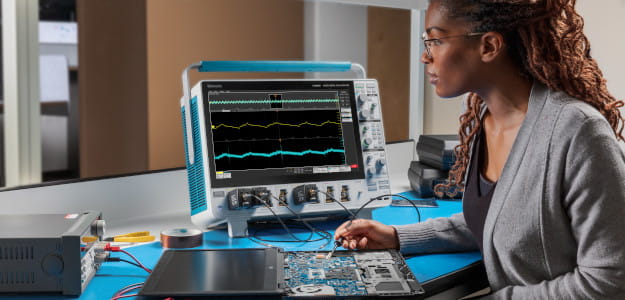
Signal integrity and power integrity are often considered separate disciplines, but we’ve seen that you need a good understanding of their differences to address these five key challenges. Fortunately, Tektronix Oscilloscopes like the 6 Series B Mixed-Signal Oscilloscope (MSO) have the necessary tools to join the two disciplines in an easy-to-use touchscreen environment.
Explore Jitter Analysis with Our Webinar
If you'd like to know more about jitter analysis, watch our webinar on signal and power integrity and learn more on Diagnosing Power Integrity and Signal Integrity Problems.