

Vector network analyzers (VNAs) can provide some of the most accurate measurements of any RF instrument. However, using poor quality or defective test port cables significantly degrades the measurement accuracy and is one of the leading causes of VNA measurement problems. Using a VNA with poor quality test port cables is like pairing a quality audio receiver with cheap speakers -- the sound quality will be limited by the quality of the speakers. If you start with the most accurate VNA in the world and use poor quality cables to connect to the DUT (device under test), your measurement results most likely will not be accurate.
RF measurements benefit from using dedicated RF cables, like those used with spectrum analyzers or signal generators. However, not all RF cables are suitable for VNA measurements. VNA users often grab whatever RF cable is laying around with no knowledge of the quality of the cable, or they use semi-rigid or conformable coax cables because they are cheap and readily available. While semi-rigid or conformable coax cables may work well in the beginning, these cables break down quickly with repeated use as they are designed to be connected once and left in place. Conformable cables lose phase stability with just a few flexes because the cable connector interfaces are not reinforced at the cable connector junction and the connector interface wears out after a small number of connections.
Other times, VNA users rely on user calibration to make up for low-quality cables and adapters. While the loss, phase and match of cables are systematic errors, correctable by user calibration, any changes to these parameters behave like drift errors and are not correctable. As a result, any movement or reconnection after user calibration introduces errors, reducing calibration stability and resulting in erroneous measurements. For a complete explanation of the errors associated with VNAs and how they are corrected, refer to the primer titled “Introduction to VNA Basics."
If the cable is bad, it follows that the measurements most likely will be wrong. In manufacturing, this could result in a good DUT being rejected, or even worse, a bad DUT being passed. In RF component design and validation, having incorrect s-parameter data could result in a costly design mistake. When performing impedance matching using a Smith chart, phase errors can cause you to waste time while trying to design a matching network or result in reduced wireless device transmission range.
Some of the potential technical problems you might encounter using poor quality cables include:
- DUT magnitude and phase errors in both reflection and transmission measurements due to phase drift of a cable. This is most often seen as a ripple in the reflection and transmission magnitude.
- Unstable or non-repeatable measurements.
- Mechanical damage to DUT or VNA port from damaged or worn out cable connectors.
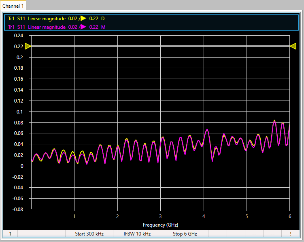
A comparison between a good (left) and bad (right) cable when bent is shown below. Here a Linear Magnitude S11 measurement is taken using the Tektronix TTR506A VNA. The purple trace is when the cable is straight. The yellow trace is when the cable is bent. Bad cables will show a larger change in magnitude and phase when bent. A good cable will have low reflections (Mag S11), and when bent it should vary minimally.


When searching for a test cable, here are some important parameters to keep in mind:
Insertion loss and phase stability. Good test port cables should not be impacted by temperature variations and should stay stable while being flexed or bent. Of course, never bend the cable beyond its minimum recommended bend radius. A good cable will typically have an insertion loss less than 2 dB, across its entire frequency range. In addition, it will have a phase stability in the order of plus or minus one or two degrees.
Reinforced cable junction between the cable and connectors. Bending the cables to calibrate or connect to the DUT puts strain on the interface between the cable and the connector. The cable can be damaged if this interface is not sufficiently reinforced.
Connection repeatability. This is the repeatability when connecting to a DUT multiple times and is largely determined by the quality of the connector on the cable.
The cable should be well-shielded. This is especially important if the measurements are done in a noisy RF environment, where EMI and electrical noise can affect the measurement signals.
The cable should have a rugged jacket. Cables used in hostile environments, where they may be bent beyond the minimum recommended bend radius, or dragged through a conduit, for example, should have a rugged jacket.
Return loss or match stability. While the return loss of the test port cable is correctable with a user calibration, the accuracy of the correction degrades as the return loss of the cable approaches zero dB. A return loss of 15 dB or greater should be sufficient for most applications. The stability of the return loss or match, however is of paramount importance. Even small changes can cause large errors if the return loss magnitude or phase changes as the cable is bent between calibration and measurement.
You may not always be the person who selected the cables and adapters available to you. Before you start making VNA measurements with whatever is available, you’ll want to run some simple tests to evaluate cable and adapter quality. In the next installment, we’ll look at the procedure for verifying cables and adapters to ensure accurate VNA Measurements.
Prior to any measurements, perform an SOL calibration on port 1. To achieve accurate results, set a low IF bandwidth and port power level to at least 0 dBm. Trace averaging may be needed to reduce the trace noise in order to see small changes in the cable. In each case, adjust the reference level to center the trace on the display and adjust the scale so the trace is somewhere between 25% and 75% of full scale. Use the marker search functions to locate the worst-case point for each measurement.
Visual inspection
Start by visually checking to see if the cable or adapter’s connectors are damaged or contaminated by any dust or particles. Sometimes even the slightest damage to the center pin can cause measurement errors, or worse, cause damage to other components while attempting to connect to them. One way to clean connectors is to use a lint-free cotton swab dampened by isopropyl alcohol, and low-pressure compressed air to dry connectors and clear away any contaminants that remain. You can also use a connector gage with the appropriate gender and type to accurately measure pin depth for comparison with the connector’s specifications.
Return loss (VSWR)
To check the cable return loss and/or VSWR, connect one end of the cable to the VNA. Connect a load to the other end of the cable, as shown below.

Test setup for cable return loss and SWR measurements using a known load.
Display S11 magnitude in dB on one trace window and SWR on another window as shown below. Use a Search > Max with a marker on each trace to find the “max” return loss value (closest to zero dB) and corresponding SWR value. Compare the measurement with the specifications of the cable. It should be noted that this measurement is only as good as the load at the end of the cable. This must be a known good load with a return loss that is better than the expected return loss of the cable.

Return loss and SWR measurement of a cable using the TTR506A VNA
In this example, the measured return loss is 23.13 dB (SWR of 1.16). This cable is performing within its specified return loss of greater than 20 dB through 7.5 GHz.
Insertion loss
Keeping the cable connected to port 1, check the cable’s insertion loss, by simply replacing the load with a short and measure S11 as you can see below. A typical insertion loss measurement requires both ports of the VNA, but in this case, in order to keep the cable straight and not have to deal with additional cabling, we leave the cable attached to port 1, use the knowledge that a short circuit produces a full reflection, and derive the cable’s loss by dividing the S11 magnitude in dB by two.

Insertion loss test setup with the cable terminated with a short.
Now display S11 magnitude in dB on one trace. Use Search > Min with a marker to find the minimum value.

Insertion loss measurement of a cable using the TTR506A VNA.
For this measurement, S11 is reading -1.79 dB. In order to get insertion loss, divide this value by 2. This gives an insertion loss of 0.90 dB. This is within the desired insertion loss of less than 2 dB, and within 1.05 dB, the insertion loss specified for the cable.
Stability of insertion loss and return loss
Use the same setups described in tests 2 and 3, except this time, with the cable straight and not moving, store the traces to memory.
· Note: to do this, with the desired trace selected, under Markers/Analysis click Display > Memory > Data -> Memory and then click Display Content > Data & Memory. See the Help for more information on this.
Use data/memory to view changes in the cable loss and phase as the cable is flexed to various positions. Hold the cable steady in each position to allow time for the VNA to complete the sweep at each position. The display will show the change in magnitude and phase of the cable.
The screen captures below show a Log Magnitude S11 and phase measurement taken using the TTR506A VNA. The purple and red traces are when the cable is straight. The yellow and green traces are when the cable is bent. Bad cables will show a larger change in magnitude and phase when bent. A good cable will have low reflections (Mag S11), and when bent it should vary minimally. This cable is performing relatively well. It should be noted that the electrical length of the cable has been removed from the phase measurements using Cal> Port Extension in order to see the phase changes with high resolution.
Since we are using a S11 measurement to characterize the transmission loss and phase, the displayed results should be divided in half to get the correct loss and phase stability.
This same procedure can be used for the case of return loss, as described in step 2.

Data-to-memory measurement of magnitude and phase for a cable terminated with a Short and flexed and bent in an effort to identify any major changes in the cable’s insertion loss.
Repeatability
To check the connection repeatability, with the cable still connected to the VNA, connect a broadband load to the other end of the cable. Display S11 magnitude. Store the trace to memory. Use Data/Memory to display the connection repeatability. Disconnect then reconnect the broadband load. The display will show the connection repeatability. Repeat several times with the broadband load rotated to different orientations.
VNA users can also minimize the introduction of errors by making the right cable connector choices in their test setups. Ideally, the connectors on test port cables should be the same, with opposite gender, as the connectors on the VNA test ports (on one end) and the connectors on the DUT (on the other end). This avoids the need to use adapters. If adapters are used, their contribution is correctable with user calibration, but the extra interface is one more connection that could come loose during calibration or measurement and the adapter will further degrade the return loss of the cable. Test port cables are available with a variety of connector options. So, when possible, choose cables to eliminate or minimize the number of adapters used in the setup and always use quality adapters.
You can spend a fortune on quality cables, but you don’t have to. Quality cables are available that perform well, are relatively affordable, and permit accurate measurement results from your VNA. Finally, even the best cables can go bad with extended use or abuse. Use the above procedures to periodically verify your cables’ and adapters’ insertion loss, return loss, phase stability and connection repeatability.
For information on quality, affordable VNA cables and adapters offered by Tektronix, see the “Accessories” tab on the TTR500 Series VNA website.

Examples of Tektronix phase-stable cables. Download the TTR500 datasheet to get a full list of available cables.
Look for more insights into making accurate VNA measurements in future blog posts.